tech notes
Small Airport Surveillance Sensor
A low-cost radar surveillance system provides airport tower controllers with improved situational awareness of aircraft at the airport and in the nearby airspace.
It may come as a surprise to the flying public that tower controllers currently monitor airport traffic mainly by looking out the window. When visibility is reduced at nighttime or during bad weather, aircraft safety and airport efficiency may be impaired. While the busiest airports have a radar-based surveillance system called ASDE-X*, it is too expensive to deploy at smaller airports.
 The SASS system has two that detect transponder replies and a master unit that determines the aircraft's location and displays it to tower controllers.
The goal of the Federal Aviation Administration-funded Small Airport Surveillance Sensor (SASS) project is to develop an inexpensive radar surveillance system for these airports. The innovative SASS design makes it possible to provide a modern phased array radar to small airports. Instead of the millions of dollars typically spent on such systems, SASS delivers the needed capability at a cost that is orders of magnitude less. The key advancement is a high-accuracy (<0.3 deg azimuth error) phased array antenna implemented with commercial off-the-shelf components.
System Design
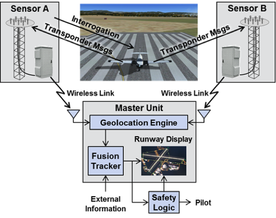
As shown in the figure, the SASS system consists of a master unit and two sensor units. The sensor units are located near the ends of the longest runway, and the master unit is located in the airport control tower. The sensor units listen for spontaneous replies from nearby aircraft equipped with Mode S beacon transponders. At least one of the sensors can also issue interrogations to aircraft with legacy ATCRBS** transponders that do not spontaneously generate replies and provide surveillance for Mode S- and ATCRBS-equipped aircraft in the surrounding airspace out to 20 nm.
The replies from nearby aircraft are passed to the master unit that computes the geographic location of surface and airborne targets, such as vehicles and aircraft. The target locations are passed to a fusion tracker that combines geographic location data with external information to produce tracks (smoothed geolocations indicating a predicted path of movement). Tracks can also be input to safety logic, providing visual and audible alarms to tower controllers and pilots.
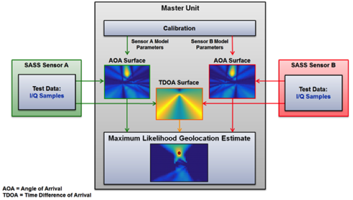 The master unit computes the maximum likelihood surfaces for the aircraft's position from each sensor's angle of arrival measurement and the time difference of arrival between the two sensors. The maximum likelihood surfaces are combined to yield the aircraft's estimated position.
Each sensor uses an eight-element phased array antenna to make high-accuracy azimuth measurements of the replies and uses GPS to record the time of arrival of the replies. The antenna array layout minimizes sidelobes while maintaining main beam accuracy. The sensors detect and decode transponder replies and then send the replies to the master unit via WiFi. The replies also contain in-phase and quadrature (I/Q) data samples used in the master unit to compute the aircraft's azimuth from the sensor.
As shown in the figure, the master unit processes the replies to obtain aircraft position and calculates the x-y coordinates for the aircraft's likely location using maximum likelihood surfaces. Angle-of-arrival likelihood surfaces are created for each sensor by fitting reply I/Q data to calibrated antenna response models, and a time-difference-of-arrival likelihood surface is created from the arrival time of the signal at both sensors. These surfaces are combined to determine the most likely location of the aircraft.
The geolocations are then passed through a Kalman filter which produces smoothed aircraft tracks that are displayed as in the figure. In this case, the SASS experimental system display with six targets being tracked simultaneously in real time (shown in red and blue below).
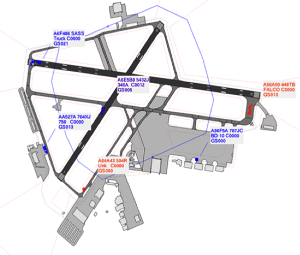 The air traffic display for the experimental SASS system at Hanscom Field in Bedford, Massachusetts, shows six targets being simultaneously geolocated and displayed in real time.
Measured Performance
The preliminary performance of the SASS experimental system set up at Hanscom Field in Bedford, Massachusetts, was assessed. The position accuracy was determined by having a GPS-equipped test vehicle furnished with a transponder drive on the runways and taxiways. The position error was computed for the region enclosed by the blue polygon in the figure where the error is expected to be 30 ft or less. The measured root mean square position error was 28 ft, which meets the position accuracy requirement.
Future Work and Impact
The performance results from the preliminary assessment are for passive surveillance of Mode S transponders. Passive surveillance of ATCRBS transponders has also been demonstrated. Although the current emphasis is on surface surveillance, passive airborne surveillance of Mode S and ATCRBS out to 0.5 nm from the runway has also been successful.
The next phase of the project is to provide an active surveillance capability using interrogations to generate replies from ATCRBS aircraft on the surface for passive surveillance and for active range-azimuth surveillance of Mode S and ATCRBS targets out to a 20 nm range.
Lincoln Laboratory seeks to work with industry to develop an affordable commercially available version of SASS for all airports lacking this all-weather surveillance capability, enabling a higher degree of situational awareness for tower controllers and pilots, and ensuring increased safety for the people and equipment arriving at or departing from small airports.
* Airport Surface Detection System—Model X
** Air Traffic Control Radar Beacon System
Posted January 2017
top of page